
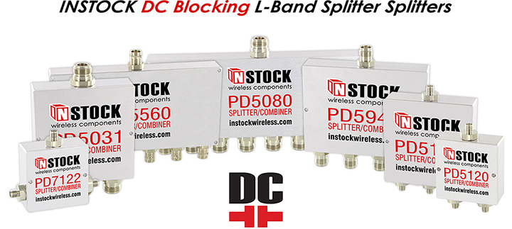
DC & 10 MHz Pass/Block L-band Splitter

L-band splitter optimized for your pass/block applications
See All New ComponentsPower Dividers, Splitters, Combiners
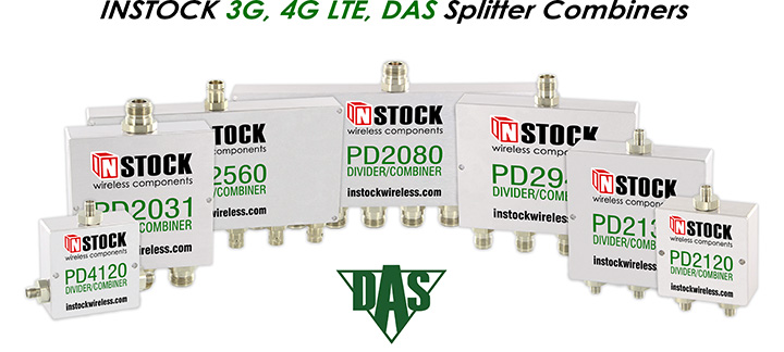
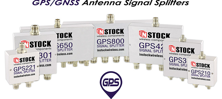
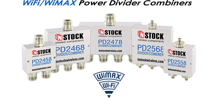
Three hundred twenty-five RF microwave power divider, combiner, splitter models to choose from in 2way thru 64way configurations. Featuring Type N, TNC, BNC, SMA, QMA, and RP-SMA 50 Ohm coaxial connectors. RF splitters and combiners available covering 350-1000 MHz, 698-2700 MHz, 1-2 GHz (GPS/GNSS), and 2.4-6.0 GHz frequency ranges. Broadband 50 ohm RF splitters span 0.698 - 2.700 GHz frequency with optimized specs for Public Safety Band, Cell, GSM 900 / 1800, PCS, UMTS, GPS, L Band, W-CDMA-3G, TETRA, IEEE802.11 b/g, UHF RFID, ISM, Wi-Fi, WiMAX and LTE wireless apps. Wilkinson microstrip design permits DC passing on all ports for active systems. DC blocking available for passive system. True 3way, 6way, 12way RF power dividers provide equal power split balance. Compact T-Style and Vertical Launch RF signal splitters offer convenient coaxial cable access. IP67 weatherproof, high power combiners and RoHS splitter combiners — INSTOCK.
Designed & Crafted in the USA … Always INSTOCK!
Since 2005, INSTOCK Wireless has proudly designed, manufactured, and distributed RF power splitter combiners from our Boonton, NJ facility. While many companies have outrageous lead times on even the smallest orders, INSTOCK Wireless keeps all products in stock. Orders placed by 6:30pm EST ship same day. All INSTOCK power dividers are designed and manufactured in the United States and include a 5 year warranty.
Challenge Us With Your Custom Splitter Combiner Requirements
Instant customization is available for all power divider combiner models. Choose your connectors (N Type, SMA, TNC, BNC, QMA, RP-SMA), circuit (350-1000 MHz, 698-2700 MHz, 1-2 GHz, 2.4-6.0 GHz), and housing (RoHS, IP67 Outdoor, Micro, Rackmount). Additional config options available. Speak with an Applications Engineer today about how we can fulfill your custom requirements by emailing sales@instockwireless.com or calling +1.973.335.6550.
Better power dividers … better prices … INSTOCK! Get pricing now!


