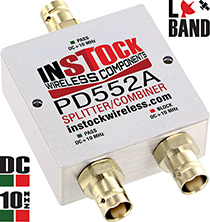
PD552A - DC Blocking Power Splitter Combiner
2 Way, BNC, 698 - 2700 MHz, Pass/Block DC + 10 MHz


USD icon click to view pricing Pop-up icon
Product Overview
- Passes 10 MHz BUC reference signal with exceptionally low 0.3 dB max insertion loss on pass port
- Blocks 10 MHz by 50 dB min on block port
- Passes DC one (1) port for powering LNB/active antenna at 4A/50 VDC max
- Equally splits full L-Band spectrum with exceptional specs
| Frequency Range |
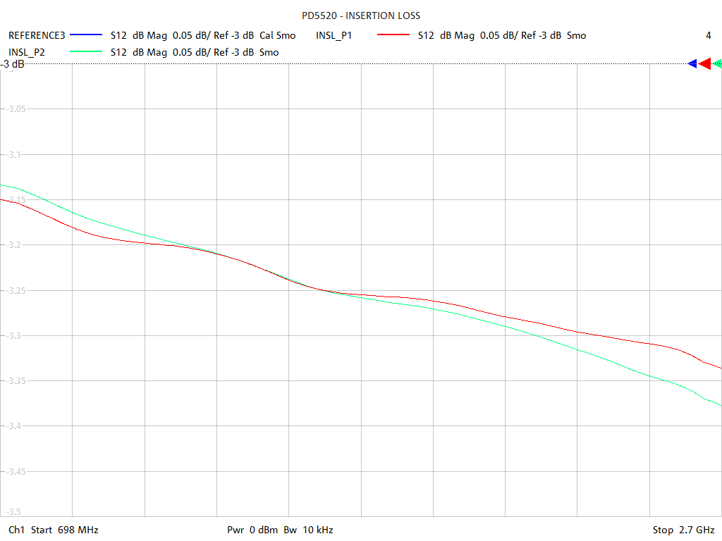
Insertion Loss |
Amplitude Balance |
Phase Balance |
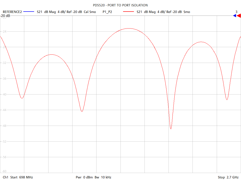
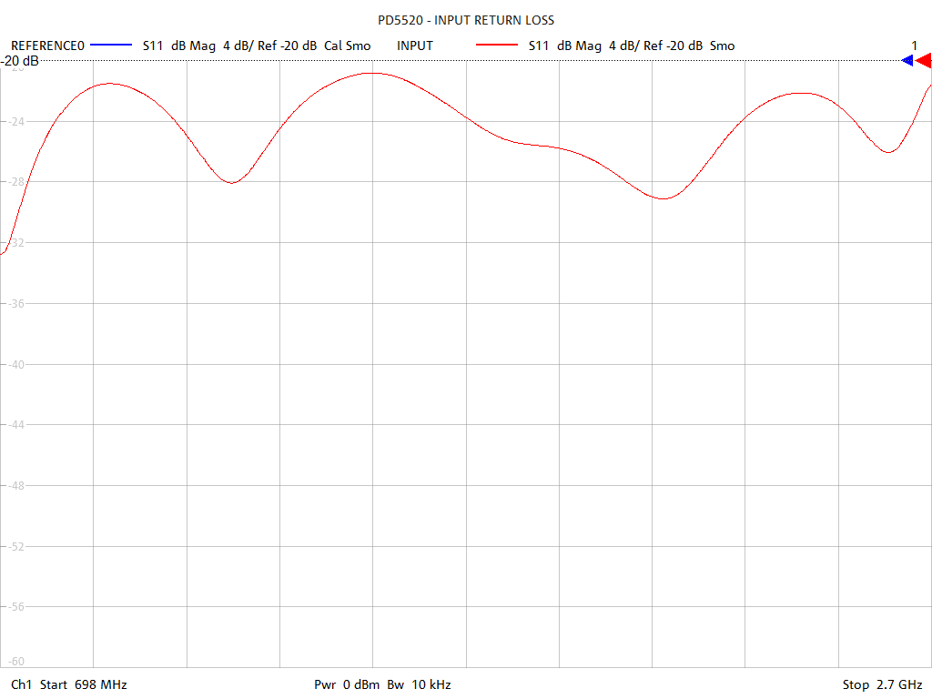
Isolation | Input VSWR |
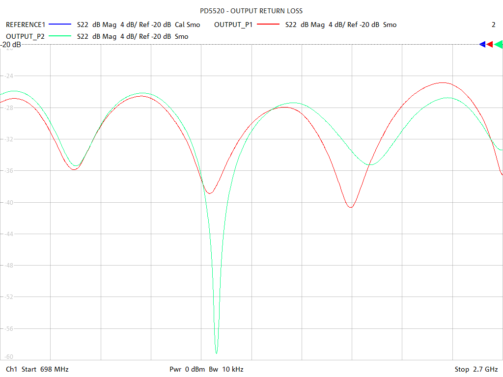
Output VSWR |
|---|---|---|---|---|---|---|
| 698-2700 MHz | 0.4 dB max* | 0.2 dB max | 6° max | 22 dB min | 1.20 : 1 max | 1.20 : 1 max |
| 10 MHz Pass | 0.3 dB max** | N/A | N/A | 50 dB min | 1.20 : 1 max | 1.20 : 1 max |
| 10 MHz Block | 50 dB min | N/A | N/A | 50 dB min | 1.20 : 1 max | 100 : 1 min |
| *Above 3.01 dB power split | **Total insertion loss | |||||
| Mechanical Specifications | |
|---|---|
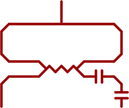
| Circuit Design | Wilkinson; DC+10 MHz pass 1 port, DC+10 MHz block 1 port |
| Connectors | BNC Female (Jack) 50 Ohm |
| Connector Body | Brass, Tri-Alloy Plate |
| Connector Pin | Phosphor Bronze, Gold Plate |
| Connector Insulator | PTFE, Virgin Electrical Grade |
| Housing | Aluminum, Clear Chem Film |
| Operating Temp | -65°C to +85°C |
| Weight | 136 Grams |
| 2 Way Power Divider RF Input Ratings | ||
|---|---|---|
| Into Matched Load VSWR's |
In-Phase | 180° Out-of-Phase |
| 1.2 : 1 | 40 Watts | 40 Watts |
| 2.0 : 1 | 40 Watts | 20 Watts |
| ∞ | 20 Watts | 2 Watts |
| 2 Way Power Combiner RF Input Ratings | ||
| Input Signals | In-Phase | 180° Out-of-Phase |
| Coherent | 2 X 20 Watts | 2 X 1 Watts |
| Non-Coherent | 2 X 2 Watts | |
PD552A Features & Benefits
Overview
PD552A is a 2-way, BNC, L-Band power divider capable of bi-directional splitting and combining in transmit and receive modes. This passive Wilkinson microstrip unit equally splits the full L-band radio spectrum between two receivers or modems while passing DC and 10 MHz through one port and blocking DC and 10 MHz from the other port.
This model is ideal for splitting L-band satellite signals between two receivers. The DC+10 MHz pass port allows one receiver to power an LNB and provides a path for the 10 MHz BUC reference signal necessary to maintain correct transmission uplink frequency. The DC+10 MHz block port prevents redundant feed from the other receiver.
A unique feature of this splitter is low insertion loss of the 10 MHz BUC reference signal thru the pass port at less than 0.3 dB compared to conventional models passing 10 MHz with approximately 3.6 dB insertion loss. This remarkably low insertion loss is achieved by filtering the 10 MHz signal from the block port, resulting in more than 50 dB rejection. This conserves virtually all the 10 MHz signal for transmission through the pass port only.
The DC pass port is rated 50VDC and 4A. All L-band applications in the frequency range from 698 to 2700 MHz are covered with best in class performance.
Electrical
The heart of the unit is a precision designed and etched Wilkinson type microstrip circuit on a low loss, high frequency, dielectric substrate. Electrical performance is highlighted by 0.4 dB max insertion loss (above the 3.01 dB power split), 22 dB min isolation, 1.20:1 max input VSWR and 1.20:1 max output port VSWR. Equal power split and symmetry is displayed by 0.2 dB amplitude balance and 3 degrees phase balance. Narrow band RF performance over your frequency range may be even better. See 2 way power divider test sweeps for details.
Mechanical
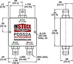
Mechanical features include precision CNC, brass, 50 ohm BNC female coaxial connectors with tri alloy plating to insure tarnish resistance and low PIM operation. Connector pins are gold plated phosphor bronze for reliability and low contact resistance. Virgin electrical grade PTFE support insulators captivate the contact pins enabling trouble free coaxial connector mating. Long term operation and superior shielding is assured by the rugged CNC machined aluminum housing with clear chemical film finish. Secure mounting is provided by two 0.125" diameter (3.18 mm) through holes. RoHS construction includes no-lead solder and a finish free of hexavalent chromium.
Physical
Housing dimensions are 1.98" wide by 1.98" deep by 0.88" high (50.3 x 50.3 x 22.2 mm). The BNC female (jack) connectors extend 0.65" (16.5 mm) from the housing. Operating temperature range is from -65°C to +85°C. Weight is 136 grams. See 2 way L-band splitter outline drawing for more information.
Applications
PD552A is ideal for splitting L-band satellite signals between two receivers. The DC+10 MHz pass port allows one receiver to power an LNB and provides a path for the 10 MHz BUC reference signal necessary to maintain correct transmission uplink frequency. The DC+10 MHz block port prevents redundant feed from the other receiver.
PD552A - 2 Way Power Divider Combiner Test Data