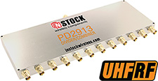
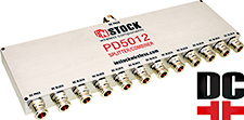
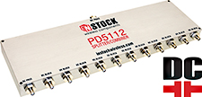
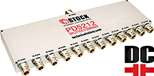
12 Way
RF Power Divider, Combiner, Splitter
Type N, SMA, TNC, BNC, 350-6000 MHz
INSTOCK twelve way power divider, power combiners are available with Type N, SMA, TNC, BNC, and QMA connector options. All models are optimized for broadband operation covering the frequency ranges from 350 to 1000 MHz, 698 to 2700 MHz, 1 to 2 GHz, and 2.4 to 6 GHz with unsurpassed electrical performance. These Wilkinson hybrid, 12 way, power divider, power combiners are reciprocal units that divide and combine signals with equal facility. Their microstrip construction will pass DC current to all ports for use in active systems. DC blocking and current steering models are also available.
Jump to 12 Way Spec Table ↴12 Way Power Divider Application Note »
12 Way Power Divider Combiner Specifications
| Model No | N Way | Coaxial Connectors |
Frequency Range (MHz) |
Insertion Loss (above split) |
Amplitude Balance (max) |
Phase Balance (max) |
Isolation (min) |
Input VSWR (max) |
Output VSWR (max) |
|---|---|---|---|---|---|---|---|---|---|
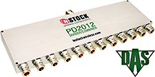
| PD2012 | 12 Way | N Type | 698-2700 | 1.5 dB | 0.5 dB | 8° | 18 dB | 1.45:1 | 1.25:1 |
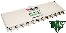
| PD2112 | 12 Way | SMA | 698-2700 | 1.5 dB | 0.5 dB | 8° | 18 dB | 1.45:1 | 1.25:1 |
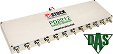
| PD2212 | 12 Way | SMA+N | 698-2700 | 1.5 dB | 0.5 dB | 8° | 18 dB | 1.50:1 | 1.25:1 |
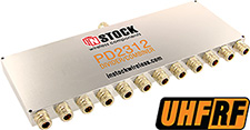
| PD2312 | 12 Way | N Type | 350-1000 | 1.4 dB | 0.4 dB | 7° | 18 dB | 1.45:1 | 1.25:1 |
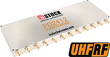
| PD2412 | 12 Way | SMA | 350-1000 | 1.4 dB | 0.4 dB | 7° | 18 dB | 1.45:1 | 1.25:1 |
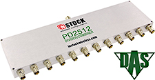
| PD2512 | 12 Way | BNC | 698-2700 | 1.5 dB | 0.5 dB | 8° | 18 dB | 1.45:1 | 1.25:1 |
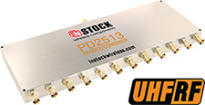
| PD2513 | 12 Way | BNC | 350-1000 | 1.4 dB | 0.4 dB | 7° | 18 dB | 1.45:1 | 1.25:1 |
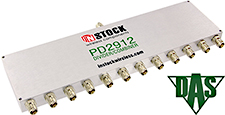
| PD2912 | 12 Way | TNC | 698-2700 | 1.5 dB | 0.5 dB | 8° | 18 dB | 1.45:1 | 1.25:1 |
| PD2913 | 12 Way | TNC | 350-1000 | 1.4 dB | 0.4 dB | 7° | 18 dB | 1.45:1 | 1.25:1 |
| PD5012 | 12 Way | N Type | 698-2700 | 1.5 dB | 0.5 dB | 8° | 18 dB | 1.45:1 | 1.25:1 |
| PD5112 | 12 Way | SMA | 698-2700 | 1.5 dB | 0.5 dB | 8° | 18 dB | 1.45:1 | 1.25:1 |
| PD5212 | 12 Way | N Type | 698-2700 | 1.5 dB | 0.5 dB | 8° | 18 dB | 1.45:1 | 1.25:1 |
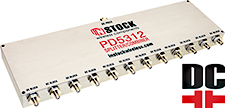
| PD5312 | 12 Way | SMA | 698-2700 | 1.5 dB | 0.5 dB | 8° | 18 dB | 1.45:1 | 1.25:1 |
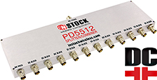
| PD5512 | 12 Way | BNC | 698-2700 | 1.5 dB | 0.5 dB | 8° | 18 dB | 1.45:1 | 1.25:1 |
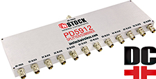
| PD5912 | 12 Way | TNC | 698-2700 | 1.5 dB | 0.5 dB | 8° | 18 dB | 1.45:1 | 1.25:1 |
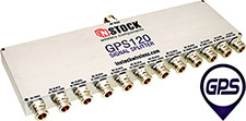
| GPS120 | 12 Way | N Type | 1000-2000 | 1.5 dB | 0.5 dB | 8° | 18 dB | 1.45:1 | 1.25:1 |
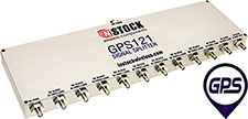
| GPS121 | 12 Way | SMA | 1000-2000 | 1.5 dB | 0.5 dB | 8° | 18 dB | 1.45:1 | 1.25:1 |
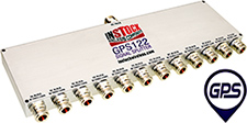
| GPS122 | 12 Way | TNC | 1000-2000 | 1.5 dB | 0.5 dB | 8° | 18 dB | 1.45:1 | 1.25:1 |
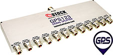
| GPS123 | 12 Way | N Type | 1000-2000 | 1.5 dB | 0.5 dB | 8° | 18 dB | 1.45:1 | 1.25:1 |
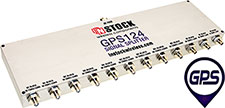
| GPS124 | 12 Way | SMA | 1000-2000 | 1.5 dB | 0.5 dB | 8° | 18 dB | 1.45:1 | 1.25:1 |
12 Way Power Divider Combiner Application Note
INSTOCK twelve way power divider, power combiners are available with two connector styles, type-N female (jack) and SMA female (jack). Both models are optimized for broadband operation covering the frequency range from 0.698 to 2.700 GHz with unsurpassed electrical performance. These Wilkinson hybrid, 12 way, power divider, power combiners are reciprocal units that can be used to divide or combine signals with equal facility. Their microstrip construction passes DC current to all ports for use in active systems.
In power dividing applications, the input signal is equally split into twelve output signals, each down 10.79 dB from the incident due to the 1:12 power division. No power is actually lost from this power split; it is just allocated into twelve amplitude and phase matched signals, thus a so called 10.79 dB insertion loss. True insertion loss of less than 1.5 dB @ max 2.7 GHz will be found at the output ports resulting from dissipation of small amounts of RF & microwave energy within the connectors and microstrip circuit. The output signals are isolated from each other by 18 dB minimum through the use of resistors that dissipate any power reflected back to the circuit caused by unequal or unbalanced output loads. The 40 watt max power rating of these power dividers is applicable when connected to matched output load VSWR of 1.2:1 or better. This maximum power rating must be reduced when load VSWR's increase and are unbalanced or out-of-phase with respect to one another. See Twelve Way Power Divider Input Ratings Table (below left) for additional guidelines.
The situation with power combining is a bit more complex. While it is possible to sum twelve input signals with no loss, this can only be accomplished if the input signals are coherent and identical in phase and amplitude. Such a case is the twelve way power splitting of a signal which is then recombined after amplification, provided the amplified signals are phase locked together. But outside this case, or cases of pure sine signals, or CW signals without any transmitted info, the combining of twelve non-coherent signals will result in a minimum 10.79 dB loss (1/12th power ratio) plus the true insertion loss of the power combiner (1.5 dB @ max 2.7 GHz). Worst-case combining loss occurs with coherent signals 180° out-of-phase, where all power is dissipated. Because the combining loss is dissipated through the isolation resistors, the power handling and heat transfer capabilities of these resistors ultimately determines the maximum combiner power rating. See 12 Way Power Combiner Input Ratings Table (left) for additional information.
Contact INSTOCK Wireless for unique solutions to your high power combiner requirements.

